


Locate UsView Larger Map |
Testimonials |
+91-94431-17233
info@abletechengineering.com
info@abletechengineering.com
DOWNLOADS
Heat exchanger type |
Maximum pressure |
Temperature range |
Fluid limitation |
Normal size ranges for individual unit |
Special features |
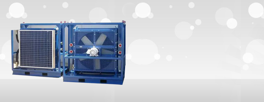
Air-cooled |
High on process side (500 bar). |
High temperature possible on process side (up to 600°C). |
Subject only to material of construction. |
5 to 350 m2 (bare tube) (per bundle multiple bundles often used). |
Heat rejection system. Requires fans. Tubes normally finned. |
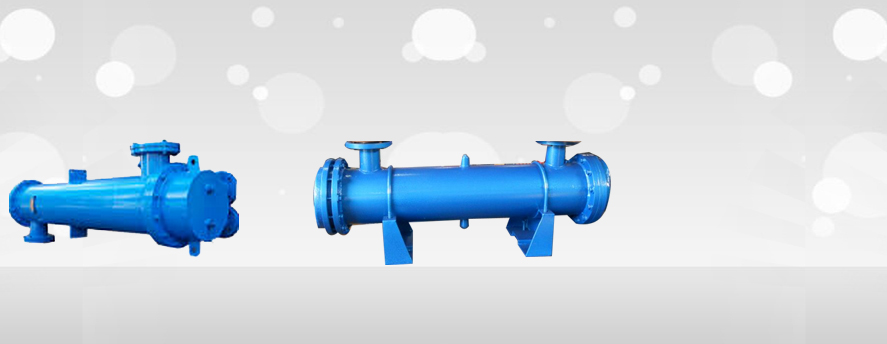
Shell and tube |
300 bar (shell). 1400 bar (tube). |
25 to 600°C (lower and higher with special materials). |
Subject only to materials of construction. |
10 to 1000 m2 (per shell multiple shells can be used). |
Very adaptable and can be used for nearly all applications. |
Brazed-plate |
16 bar |
Up to 200°C. |
Suitable for liquids compatible with braze material. |
1 to 10 m2 . |
Modular construction.not easily cleaned. |
Double-pipe (plain and finned tubes) |
300 bar (shell) (higher pressures possible with special design). 1400 bar (tube). |
100 to 600°C (higher with special materials). |
Subject only to materials of construction. |
0.25 to 200 m2 per unit multiple units are often used. |
High thermal efficiency, standard modular construction. |
Electric tubular heat exchangers |
300 bar |
Up to 700°C. |
Subject only to materials of construction. |
3 to 650 kW. Multiple units used for larger capacity. |
Special control systems can be used to minimise impact on electrical supply. |
Glass-tube |
c. 1 bar |
Up to 250°C. |
Low pressure, suitable for corrosive fluids. |
Stainless steel often used in structure. |
|
Graphite |
20 bar |
50°C to 165°C. |
Corrosion resistant unless fluid attacks resin. |
0.2 to 60 m2. |
High corrosion resistance. |
Spiral |
18 bar |
Up to 400°C |
Subject only to materials of construction. Often used for fouling duties. |
Up to 200 m2. |
High heat transfer efficiency. Cylindrical geometry useful as integral part of distillation tower. |
Heat-pipe |
Near atmospheric. |
<200°C (higher with special heat pipe fluids). |
Low pressure gases. |
100 to 1000 m2. |
Near counter-flow operation possible. Extended surface possible on both sides. |
Plastic tube |
1 bar |
Up to 100°C. |
Low pressure,suitable for corrosive fluids. |
Stainless steel often used in structure. |
|
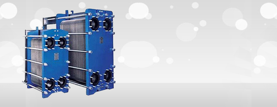
Plate-and-frame |
25 bar with some models up to 40 bar. |
25 to 175°C (40 to 200°C possible for very special types) |
Normally unsuitable for gases. Limitation is on gaskets. |
1 to 2500 m2 |
Modular construction. Normally the most economical if applicable. |
Plate-fin |
100 bar (aluminium). 200 bar (stainless steel), |
273 to + 150°C (aluminium) (up to 600°C in stainless steel), |
Low fouling. |
<9 m volume |
Very small AT possible. Incorporation of multiple streams. Very large surface area per unit volume. |
Printed-circuit |
1000 bar |
800°C (with stainless steel materiallimited). |
Low fouling. |
to 1000 m2 |
Very large surface area per unit volume. Stainless steel or higher alloys normal construction material. |
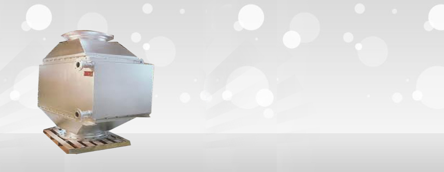
Rotary regenerators |
Near atmospheric, |
Up to 980°C. |
Low pressured gases. |
Inter-stream leakage must be tolerated |
|
Scraped- surface |
10 bar. |
Up to 300°C. |
Liquids subject only to materials of construction. |
5 to 10 m height, 0.5 m dia. |
Suitable for viscous and crystallisation systems |
Welded-plate |
60 bar (higher in shells). |
In excess of 65 0°C. |
Subject only to materials of construction. Not suitable for fouling duties. |
> 1000 m2 |
Differential pressure should be less than 30 bar. Differential expansion should be borne in mind. |
Basic Concepts of Heat Exchange
Heat exchange is a natural phenomenon occurring between fluids of different temperatures. Heat exchangers allow to control heat transfer and are used for various applications, such as radiant heating, solar heating, ice and snow melt, oil cooling and pre-heating, domestic water heating, and more.
Theoretical Heat Transfer
The basic principal of heat exchangers is based on the premise that colder fluid gains heat from a relatively hotter fluid while flowing over a conductive material in a heat exchanger. This is expressed by the following formula:
Qt = m x Cp x ∆T, where:
Q (Bth/h) = Total heat load
m (lbs/h) = Mass flow rate of fluid
Cp (Btu/F, lbs) = Specific heat of fluid at constant pressure
∆T (F) = Change in temperatures between inlet and outlet of the fluid
This formula gives us theoretical heat load from a given fluid undergoing ∆T temperature change at a mass flow rate m, with the fluid’s specific heat capacity Cp. It is a theoretical heat yield that can be transferred to or from a fluid.
Practical Heat Transfer
While theoretical heat load gives us an idea of the amount of heat that can be transferred to or from a fluid; the practical heat transfer also depends on the fluid properties, materials of contraction of the heat exchanger and physical geometry of the heat exchanger itself.
Practical heat transfer can be defined as the maximum potential heat transfer through a heat exchanger and is expressed by the following formula:
Qp = U x A x LMTD, where:
U = Overall heat transfer coefficient
A = Surface area
LMTD = Logarithmic mean temperature difference of the inlet and outlet temperatures
In turn, logarithmic mean temperature difference for counter flow heat exchangers is expressed by the following formula:
LMTD=[(Thi-Tco)- (Tho-Tci) ]/(ln[(Thi-Tco)- (Tho-Tci)]) , where:
Thi = Inlet temperature of hotter fluid
Tho = Outlet temperature of hotter fluid
Tco = Outlet temperature of colder fluid
Tci = Inlet temperature of colder fluid